


Magnetic AFM Probes
Magnetic AFM Probes

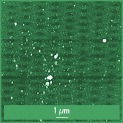
Co-Cr coated AFM tip close-up
Typical radius of uncoated AFM tip
8nm
Resulting AFM tip radius with the coating
<60nm
Full AFM tip cone angle
40°
Total AFM tip height
12-18µm
AFM Probe material
n-type silicon
AFM Tip coating
Magnetic
Detector coating
Aluminum
The coating consists of a Co layer on the tip side of the AFM cantilever. The Co layer is formed as a polycrystalline film, which allows steady permanent magnetization in the direction of the AFM tip axis. The Co coating is protected from oxidation by a thin Cr layer, resulting in longer AFM cantilever performance. The typical coercivity Hc of the Co-Cr coating ranges from 300Oe to 400Oe.
All chips are pre-magnetized at the facility before shipping to end users. In some cases additional magnetization by an arbitrary strong magnet is required, e.g. SmCo or NdFeB.
The AFM tips have trihedral shape with a full cone angle of 40° and even smaller at the last 200nm of the AFM tip apex.
1-AFM Cantilever Series
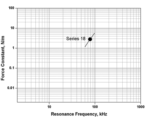
| AFM Cantilever | Resonance Frequency, kHz | Force Constant, N/m | ||||
|---|---|---|---|---|---|---|
| min | typical | max | min | typical | max | |
| 18 series | 60 | 75 | 90 | 1.2 | 2.8 | 5.5 |
3-AFM Cantilevers Series
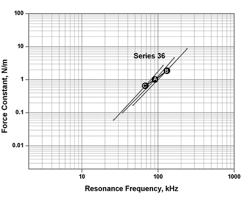
| AFM Cantilever | Resonance Frequency, kHz | Force Constant, N/m | |||||
|---|---|---|---|---|---|---|---|
| min | typical | max | min | typical | max | ||
| 36 series | Cantilever A | 30 | 60 | 160 | 0.1 | 1.0 | 4.6 |
| Cantilever B | 45 | 130 | 240 | 0.2 | 2 | 9 | |
| Cantilever C | 25 | 65 | 115 | 0.06 | 0.6 | 2.7 | |
Application
AFM probes with magnetic Co-Cr AFM tip coating can be used for Magnetic Force Microscopy (MFM) research. Mapping of magnetic stray field distribution to topography AFM scans can help characterize the domain structure of the magnetic materials.
The Co-Cr coating on most MFM probes creates a magnetic moment of about 10-13emu. Imaging in external magnetic field is a way to enhance the sensitivity further as it may increase the moment of both the MFM tip and the sample. Note that the magnetic structure of some samples having low coercivity (permalloy, garnet films, etc.) may be significantly affected by the magnetized Co-Cr coated AFM probe.
Though chromium provides protection for cobalt from oxidizing, magnetic AFM probes have a limited shelf life that ranges from weeks to months that depends mostly on humidity. However, there may be other reasons why AFM probes lose sensitivity. Sometimes, magnetization with an arbitrary strong magnet may help to restore the AFM probes, e.g. SmCo or NdFeB.

Height and phase images of the magnetic dipoles obtained using Co-Cr AFM cantilevers. The structure is formed in a layer of Fe0.7C0.3 by annealing with interfering laser impulses . Images are courtesy of Prof. Sheviakov (MIET, Moscow).
HQ:NSC18/Co-Cr/Al BS
Magnetic Force Microscopy AFM Probe
AFM probes of the HQ:NSC18 series are suitable for soft tapping and Lift mode operation AFM (e.g. EFM and MFM) since they provide high stability in tapping mode as well as high sensitivity to magnetic and electric forces that may be weak. These AFM probes are also used for mapping of materials properties in Force modulation mode and true topography imaging of soft samples in Soft tapping mode.
The HQ AFM probes offer high consistency of the AFM tip radius, the AFM cantilever reflectivity and the quality factor.
The coating consists of a cobalt layer on the tip side and an aluminum reflective layer on the back side of the AFM cantilever. The cobalt layer is formed as a polycrystalline film, which allows steady permanent magnetization in the direction of the tip axis.
All AFM probes are pre-magnetized at the facility before shipping to end users. In some cases additional magnetization by an arbitrary strong magnet is required, e.g. SmCo or NdFeB. The cobalt coating is protected from oxidation by a thin chromium layer, resulting in longer AFM tip lifetime. The aluminum reflective coating enhances the laser reflectivity of the AFM cantilever by approximately 2.5 times.
Magnetic


![]()


AFM Probe Specifications
AFM Tip
| Shape | Height | Full Cone Angle | Radius |
|---|---|---|---|
| Rotated | 15 µm (12 - 18 µm) | 40° | < 60 nm |
AFM Cantilever
| Cantilever | Shape | Force Const. | Res. Freq. | Length | Width | Thickness |
|---|---|---|---|---|---|---|
| Cantilever A | Beam | 2.8 N/m(1.2 - 5.5 N/m) | 75 kHz(60 - 90 kHz) | 225 µm(220 - 230µm) | 27.5 µm(24.5 - 30.5µm) | 3 µm(2.5 - 3.5 µm) |
All typical values
HQ:NSC36/Co-Cr/Al BS
Magnetic AFM Probe with 3 Different AFM Cantilevers
AFM probes of the HQ:NSC36 series have three different soft tapping mode AFM cantilevers on one side of the holder chip. They can be used in various applications.
The HQ AFM probes offer high consistency of the AFM tip radius, the AFM cantilever reflectivity and the quality factor.
The coating consists of a cobalt layer on the tip side and an aluminum reflective layer on the back side of the AFM cantilevers. The cobalt layer is formed as a polycrystalline film, which allows steady permanent magnetization in the direction of the tip axis.
All AFM probes are pre-magnetized at the facility before shipping to end users. In some cases additional magnetization by an arbitrary strong magnet is required, e.g. SmCo or NdFeB. The cobalt coating is protected from oxidation by a thin chromium layer, resulting in longer AFM tip lifetime. The aluminum reflective coating enhances the laser reflectivity of the AFM cantilevers by approximately 2.5 times.
Magnetic


![]()


AFM Probe Specifications
AFM Tip
| Shape | Height | Full Cone Angle | Radius |
|---|---|---|---|
| Rotated | 15 µm (12 - 18 µm) | 40° | < 60 nm |
AFM Cantilever
| Cantilever | Shape | Force Const. | Res. Freq. | Length | Width | Thickness |
|---|---|---|---|---|---|---|
| Cantilever A | Beam | 1 N/m(0.1 - 4.6 N/m) | 60 kHz(30 - 160 kHz) | 110 µm(105 - 115µm) | 32.5 µm(29.5 - 35.5µm) | 1 µm(0.5 - 1.5 µm) |
| Cantilever B | Beam | 2 N/m(0.2 - 9 N/m) | 130 kHz(45 - 240 kHz) | 90 µm(85 - 95µm) | 32.5 µm(29.5 - 35.5µm) | 1 µm(0.5 - 1.5 µm) |
| Cantilever C | Beam | 0.6 N/m(0.06 - 2.7 N/m) | 65 kHz(25 - 115 kHz) | 130 µm(125 - 135µm) | 32.5 µm(29.5 - 35.5µm) | 1 µm(0.5 - 1.5 µm) |
All typical values
Documentation
Documentation


Total items
Product subtotal