


AFM Test Gratings
AFM Test Gratings
Block Test Gratings for Z-axis

Selection of 3 block type test gratings with different step heights intended for Z-axis calibration of scanning probe microscopes and linearity measurements.

| Structure: Pattern type: Step heights: Period: Chip size: Effective area: |
Si Wafer with SiO2 layer for grating 1-Dimensional (in Z-axis direction) 20±1.5nm for TGZ-20 110±2nm for TGZ-100 520±3nm for TGZ-500 3 ±0.01µm 5 x 5 x 0.5mm Central square of 3 x 3mm |
Note: Values for step heights are nominal; actual step height is given with the product and could be ±5%
Triangular Test Grating for X- or Y-axis

The TGT-1500 test grating is intended for SPM calibration in X- or Y-axis, determination of lateral and vertical scanner nonlinearity, detection of angular distortion and tip characterization. Nominal values for height and pitch are given below. Actual values come with the test grating.

| Structure: Pattern type: Edge angle: Edge Radius: Pattern Height: Pitch: Chip size: Effective area: |
Si wafer with grating in top surface 1-D array of triangular steps with precise linear and angular dimensions approximately 70 degrees ≤10nm 1.8µm - non-calibrated, for information only 3 ±0.01µm 5 x 5 x 0.5mm Central square of 3 x 3mm |
Test Grating for Tip Sharpness

The TGTZ-400 test grating is intended for 3-D visualization of the scanning tip, determination of tip sharpness parameters, tip degradation and contamination control.

| Structure: Pattern type: Tip angle: Tip radius: Tip height: Period: Diagonal period: Chip size: Effective area: |
Si wafer with grating in top surface Array of sharp tips About 50 degrees ≤10nm 0.3 - 0.7µm 3 ±0.01µm 2.12µm 5 x 5 x 0.5mm Central square of 2 x 2mm |
Test Grating for Lateral Calibration

The TG3D-3000/600 test grating with its 3-Dimensional array is intended for lateral calibration of SPM scanners, detection of lateral nonlinearity, hysteresis, creep, cross-coupling effects and for determination of the tip aspect ratio.


| Structure: Pattern type: Height: Top square size: Edge radius: Period: Chip size: Effective area: |
Si wafer with grating in top surface Chessboard like array of square pillars with sharp undercut edges 0.3 - 0.6µm 1.2 x 1.2µm ≤10nm 3 ±0.05µm 5 x 5 x 0.5mm Central square of 3 x 3mm |
Note: Height and top square dimensions are given for information only (non calibrated values).
Test Grating for X-, Y- and Z-direction

The TG3D-3000/20 test grating with its truly 3-Dimensional structure is intended for simultaneous calibration in X-, Y- and Z-direction, lateral calibration of SPM scanners and detection of any lateral nonlinearity, hysteresis, creep and cross-coupling effects.

| Structure: Pattern type: Height: Square size: Period: Chip size: Effective area: |
Si wafer with SiO2 layer for grating 3-Dimensional array of small squares 20 ±1.5nm 1.5 ±0.15µm 3 ±0.05µm 5 x 5 x 0.5mm Central square of 3 x 3mm |
Note: The precision on the height is based on the measurement of 5 gratings (randomly selected from a batch of 300 gratings) by an SPM calibrated by a PTB certified TGZ-20 grating. The basic step height can vary from the specified one within 10% (example: step height can be 22 ±1.5nm).
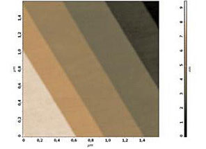
SiC-STEP Calibration Samples

SiC/0.75

SiC/1.5
6H-SiC (0001) based calibration sample which is designed to perform easy calibrations of an AFM scanner's vertical movements in several nanometers interval. The simplicity of calibration of the calibration process is provided by the nearly uniform distribution of half-monolayer high steps (either 0.75 or 1.5nm) on the sample surface demonstrating both chemical and mechanical stability. The step height corresponds to the half of the lattice constant of the 6H-SiC crystal in the (0001) direction.
PELCO® Technical Notes for SiC-STEP Calibration Sample (147K pdf)
| Specifications: | SiC / 0.75 | SiC / 1.5 |
|---|---|---|
| Structure: | SiC with Steps | |
| Single Step Height: | 0.75nm | 1.5nm |
| Average Inter Step Distance: | 0.15-0.4µm | 0.2-0.5µm |
| Misorientation of Surface: | ~0.2° | ~0.3° |
| Average Roughness of Area Between Steps (terraces): | 0.09nm | |
| Chip Size: | 5 x 5 x 0.3mm | |

SiC/0.75

SiC/1.5
Documentation
Documentation


Total items
Product subtotal